- Développé principalement pour une utilisation avec des charges en courant continu ininterrompu, mais peut aussi être utilisé avec des courants alternatifs.
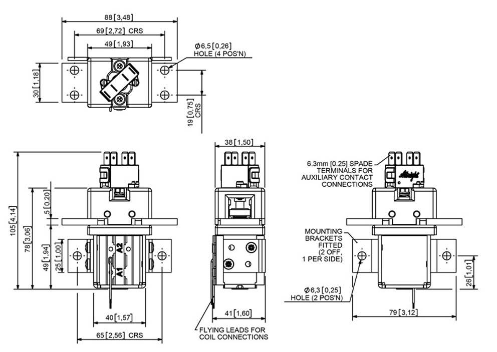
- Conçu pour être installé dans les limites d’un rack 1U du système de distribution d’énergie.
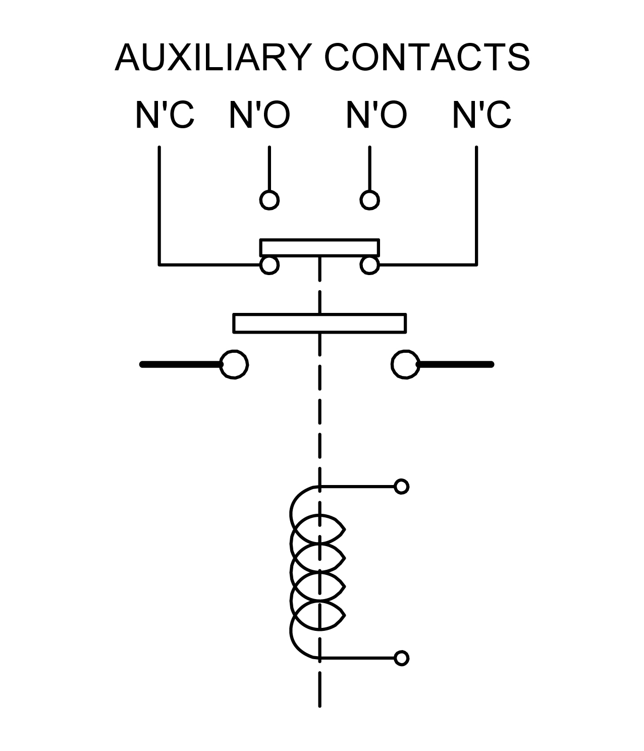
- Connexions ou câbles volants de 6,3 mm.
- Options de montage adaptable, dans n’importe quelle orientation (demandez conseil technique pour des considérations complètes sur le montage).
SW225 Technical Info
| Application | InterruptedRating (Ith) | UninterruptedRating (Ith) |
|---|---|---|
| Thermal Current Rating | A | 225A |
| Intermittent Current Rating: | ||
| 30% Duty | A | 410A |
| 40% Duty | A | 355A |
| 50% Duty | A | 320A |
| 60% Duty | A | 290A |
| 70% Duty | A | 270A |
| Rated Fault Current Breaking Capacity (lcn) 5ms Time Constraint: (In accordance with UL583*) | ||
| Blowouts | A at V D.C. | |
| No Blowouts | A at V D.C. | |
| Rated Fault Current Breaking Capacity (lcn) Resistive Load: (In accordance with UL508*) | ||
| Blowouts | A at V D.C. | |
| No Blowouts | 330A at 60V D.C. | |
| Maximum Recommended Contact Voltages | ||
| Blowouts | V | V |
| No Blowouts | 60V | 60V |
| Typical Voltage Drop per pole across New Contacts at 225A | 40mV | |
| Mechanical Durability | >0 Cycles | |
| Coil Voltage Available (Us) (Rectifier board required for A.C.) | >6 - 240V | |
SW225 Features
Click on an optional feature to automatically add this selection to the enquiry form below
| Component | Configurations |
|---|---|
| Auxiliary | |
| Coil Suppression | |
| Coil Termination | |
| Fixed Contact Terminal | |
| Magnetic Latching | |
| Manual Override | |
| Mounting | |
| Vacuum Impregnation |